.
In this manner, what is the difference between common anode and common cathode?
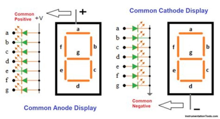
Common anode means that the anode (positive) side of all of the LEDs are electrically connected at one pin, and each LED cathode has its own pin. Common cathode means that the cathodes of all of the LEDs are common and connected to a single pin. The anode for each LED has its own pin.
Beside above, how do you test common anode 7 segment display using a multimeter? Checking 7-Segment Display
- Hold the display in your hand and identify pin 1.
- Now take the multimeter (assuming a red lead for positive and a black lead for negative) and set it to the proper continuity range.
- Check your meter with a sound test (touch both the leads together, and a sound will be produced).
Also know, how do you use the common cathode 7 segment display?
Common Cathode 7-Segment Display
- For common cathode make GND pin ground.
- Apply +5 volts to dp(decimal/display point) pin in series to a 510 ohm-1k ohm resistor to limit the current.
- Now if your small circle led lit's it means that your seven segment is properly working and now you can use it.
Which is better common anode or cathode?
High-side (anode) drivers are more expensive, so the number of them has to be minimized. If the digits are not multiplexed, common cathode is better. If the digits are multiplexed, and there are less than 7–8 digits, common cathode is better. With more than 8 multiplexed digits, common anode is better.
Related Question AnswersIs an anode negative or positive?
In a galvanic (voltaic) cell, the anode is considered negative and the cathode is considered positive. This seems reasonable as the anode is the source of electrons and cathode is where the electrons flow. However, in an electrolytic cell, the anode is taken to be positive while the cathode is now negative.What is common anode display?
The Common Anode (CA) – In the common anode display, all the anode connections of the LED segments are joined together to logic “1”. The individual segments are illuminated by applying a ground, logic “0” or “LOW” signal via a suitable current limiting resistor to the Cathode of the particular segment (a-g).How do you tell if RGB LED is common anode or cathode?
Distinguish between RGB LED common anode and common cathode Place the red multimeter tip on the longest LED lead. Then, place the black tip on one of the other leads. If the LED lights up, this means you have a common anode LED.What is an anode and cathode?
Definition: The anode of a device is the terminal where current flows in from outside. The cathode of a device is the terminal where current flows out. By current we mean the positive conventional current. Since electrons are negatively charged, positive current flowing in is the same as electrons flowing out.Which side of an LED is positive?
The longer leg is the positive side of the LED, called the “anode,” and the shorter leg is the negative side, called the “cathode.” Within an LED, current can only flow from the anode (positive side) to the cathode (negative side) and never in the opposite direction.How does a 7 segment display work?
A 7 segment display is made of seven different illuminating segments. These are arranged in a way to form numbers and characters by displaying different combinations of segments. The binary information is displayed using these seven segments. These LED's or LCD's are used to display the required numeral or alphabet.Do 7 segment displays need resistors?
A current limiting resistor is required for each segment of a 7-segment display. Each resistor provides a voltage drop for each diode in the segment. An advantage of this circuit is that all the LEDs will light with equal intensity, because each has the same amount of current passing through it.How do you find common anode 7 segment display?
This will avoid potential damage to the LED's in the display. Next, connect the resistor to the positive terminal (either battery or supply) and then connect any of the A-G segments to 0V or GND. If the LED lights up, it is common ANODE. If no segment lights up then you need to reverse the wiring.How do you connect common anode 7 segment display to Arduino?
In a common anode display, the positive terminal of the eight-shaped LEDs are connected together. They are then connected to pin 3 and pin 8. To turn on an individual segment, one of the pins is grounded. The diagram below shows the internal structure of the common anode seven-segment display.How do you light a 7 segment display?
Position the 7 Segment Display so that the top row of pins are separated from the lower pins by the center gutter that divides the breadboard. Then connect a jumper wire from the resistor to pin 1 of the display. Finally, touch a jumper from the ground rail to pin 2 of the display as shown on the above diagram.What are the applications of seven segment display?
Applications of Seven Segment Displays are these displays are commonly used in timers, clock radios, digital clocks, calculators and wristwatches. These devices can also be found in speedometers, motor-vehicle odometers, and radio frequency indicators.How do I create a 7 segment display?
How to Make 7 Segment Digit- Step 1: Watch This Video.
- Step 2: Material List. Thermocol,
- Step 3: Print 7 Segment Digit Image. Print this image in a paper.
- Step 4: Cut the Layout.
- Step 5: LED Fixing.
- Step 6: Connection.
- Step 7: Connect All Anode.
- Step 8: Connection of Cathode.